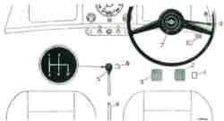
| 1 Accelerator pedal
2 Brake pedal 3 Clutch pedal 4 Hand brake 5 Gear lever |
6 Headlight dip switch
7 Horn-push 8 Direction indicator 9 Direction indicator warning light 10 Bonnet pull |
Text and graphics reproduced from the original handbook.
Controls and Instruments
Gear Lever
The gear lever is centrally situated: first and second gears are
selected by moving the lever to the left, and engaged by moving it forwards
for first gear or backwards for second gear. Third and fourth gears
are selected by moving the lever to the right through the neutral position
until resistance is felt, then forwards for third gear and backwards for
fourth gear.
To engage the reverse gear move the lever to the right in the neutral
position until resistance is felt, continue moving the lever to the right
against the spring pressure until the stop is reached, and then move it
backwards to engage the gear.
|
|
Pedal Controls
The pedal controls are arranged in the orthodox positions namely,
the clutch pedal, brake pedal, and accelerator, reading from left to right.
Do not drive with your foot resting on the clutch pedal.
Hand Brake
Pulling the lever upwards operates the rear wheel brake shoes mechanically.
Release the brake by pulling on the lever to take the load and then pressing
on the ratchet release button with the thumb before pushing the handle
downwards into the off position.
Ignition and Starter Switch
The ignition and starter switch is located in the control panel
and is operated by a removable key, which also serves to lick the drivers
door.
To switch on the ignition insert the key and turn it in a clockwise
direction until a slight resistance is felt. Further movement in
the same direction will operate the starter motor. Release the key
immediately the engine starts. If the engine fails to start first
time wait until it has come to rest before using the starter again.
Never leave the switch in the on position when the engine is not
running.
Ignition Warning Light
The ignition warning light serves the dual purpose of reminding
the driver to switch off the ignition and of acting as a no-charge indicator.
With the ignition switched on the warning light should only be illuminated
when the engine is not running or is running at a very low speed.
As the engine speed is increased the light should dim and then go out at
a fairly low engine speed.
If the light fails to go out until higher engine speeds are reached or remains alight at all times, inspect the dynamo driving belt for correct tension or breakage. If the belt is in order, the charging system must be overhauled by a Distributor or Dealer.
Choke or Mixture Control
To enrich the mixture and to assist starting when the engine is
cold pull out the control knob positioned on the right of the panel.
The control will hold in any position, giving a progressively richer mixture
as it is pulled farther out.
On no account should the engine run for any length of time with
the knob pulled fully out. It should be returned to the off position
(pushed in) as soon as possible as the engine warms up.
The first 6mm approximately of movement operates only the throttle
control. This initial movement can be used to give a fast engine
idling speed and prevent stalling when driving at low speeds before the
engine has fully warmed up. This will not be detrimental to the engine,
but do not run the engine for any length of time with the knob withdrawn
beyond this.
Lighting Switch
The headlight and pilot light switch is positioned to the right
of the ignition switch on the panel.
The pilot lights and tail lights are brought into operation when
the switch is moved downwards to the central position. Further downward
movement of the switch to the lower position switches on the headlights.
Headlight Bean Dipping Switch and Warning Light
The headlight beam dipping switch is situated in the centre of the
toeboard. It is of the single-acting repeating type, dipping the
light beams on one depression and raising the beams on the next depression.
A warning light at the bottom of the instrument panel will glow
blue when the headlight beams are in the raised position.
Windscreen Wiper Switch
The windscreen wiper switch is positioned on the left of the ignition
switch. Move downwards to switch on the wipers, which will function
only if the ignition is on. Park the blades by switching off at the
end of the stroke when the blades are in the required position.
Horn Switch
Pressing the centre disc of the steering wheel sounds the horn.
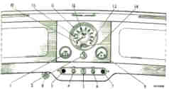
Fuel Level Gauge, Oil Pressure Gauge
The fuel level gauge is clearly marked and is incorporated in the
speedometer dial. To the right of the speedometer is an oil pressure
gauge, which should read approximately 60lb/sq in under normal running
conditions.
Lubrication Warning Light
The lubrication warning light is your guide to the need for more
frequent oil and filter change.
 |
|
Flashing Direction Indicators
A lever switch fitted on the steering-column operates the flashing
indicators (when the ignition is switched on). On right-hand drive
models the switch lever is moved upwards for the left-hand flashing indicators
and downwards for the right-hand flashing indicators. On left-hand
drive models this action is reversed.
A warning light in the end of the switch lever shows when either
indicator is flashing.
Instrument Lights Switch
Located at the lower centre of the instrument panel. Press
down to switch on the instrument lights which can only be used when the
pilot lights are on.
Interior Lamp
The interior lamp is controlled by a switch on the lamp and by automatic
switches on the door pillars.
Water Temperature Gauge
The temperature gauge indicates the temperature of the coolant entering
the radiator from the cylinder head. After the initial rise in temperature
during the warming-up period any undue upward change in reading calls for
immediate investigation. The gauge will not react instantaneously
to changed conditions, but will do so slowly.
HEATER
Fresh Air Heater (when fitted)
The fresh air heater can be used for heating and ventilating the
interior of the car and also for demisting and defrosting the windscreen.
Heat Control
The left-hand knob on the switch panel regulates the amount of hot
water circulating in the heater system. The maximum amount of heat
is available when the knob is pushed fully in. Any position of the
knob can be selected to meet varying conditions. On export models
where the equipment is used for the purpose of introducing only unheated
fresh air into the vehicle, the heat control is not fitted.
Air Distribution
The lever projecting from the front face of the heater box at its
centre controls the air distribution shutter and can be set in any one
of three positions. When set in the top (CAR) position air is distributed
mainly to the interior of the car, with some to the windscreen. In
the centre (SCREEN) position air is directed onto the windscreen.
The supply of air is cut off when the lever is in the lowest (OFF) position.
Blower Motor and Switch
The blower motor greatly increases the supply of air to the heater
unit, and thus the volume of heat output.
The blower should be switched on when maximum performance from the
heating or ventilating system is required, or to compensate for the lack
of ram effect at the air intake when the vehicle is travelling at low speed.
The switch for the blower motor is located on the lower forward face of
the heater box at its centre and operates with a side-to-side movement.
Note: Should unpleasant fumes be drawn in from outside, switch off
the blower motor and set the shutter operating lever in the OFF position
until outside conditions improve.